14 Results
View results:
Sort by:
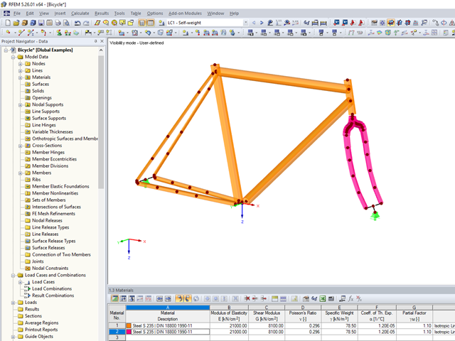
In RFEM and RSTAB, you can simulate extensive complex models from different materials in one computing environment.

In the "Edit Load Cases and Combinations" dialog box, you can combine different load cases in one load combination under the "Load Combinations" tab.

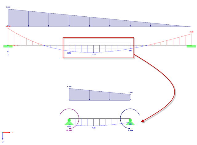
You can use the "Free Circular Load" option in RFEM to apply a partial uplift force to a cone‑shaped floor slab. It can be defined as linearly variable. The definition of center C and the outer boundary R can be specified easily, using the select function.

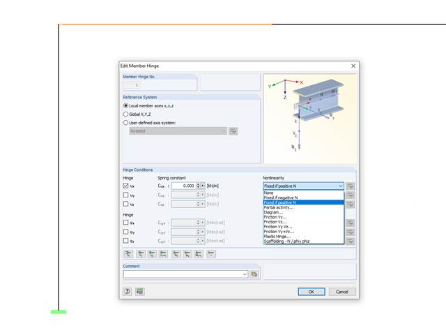
In RFEM 5 and RSTAB 8, it is possible to assign nonlinearities to member hinges. In addition to the nonlinearities "Fixed if" and "Partial activity", you can select "Diagram". If you select the "Diagram" option, you have to specify the according settings for the activity of the member hinge. For the individual definition points, it is necessary to specify the abscissa and ordinate values (deformations or rotations and the according internal forces) that define the hinge.
In RFEM and RSTAB, it is possible to define nonlinear properties of member releases. In addition to the activity diagrams and force-deformation relationship, you also have the simple option of using signs or limit values of the internal forces as criteria for the effectiveness of the release. This way, you can specify which internal forces should be transferred at the member end.

In addition to the basic combination rules of EN 1990, there are other combination conditions for actions on road bridges specified in EN 1991‑2 that must be taken into account. RFEM and RSTAB provide automatic combinatorics that can be activated in the General Data when selecting the standard EN 1990 + EN 1991‑2. The partial safety factors and combination coefficients depending on the action category are preset when selecting the respective National Annex.

According to Clause 7.3.2 (2), standard DIN EN 1992-1-1 requires: "In profiled cross‑sections like T‑beams and box girders, the minimum reinforcement should be determined for the individual parts of the section (webs, flanges)." In the case of a floor beam with a T‑section, the minimum reinforcement should be determined for both flanges and the web if the corresponding partial cross‑sections are in the tension area. Image 01 shows the division into partial cross-sections.
![Design Model for Bonded Joint Resistance According to [1]](/en/webimage/009526/2419234/01-en-png.png?mw=640&hash=c76563b459152b19c98197ea6ba342be89d9a5bc)
In the construction process, it is often necessary to fabricate the concrete elements in sections. A classic example of this production in sections is the use of prefabricated downstand beams, in which the slab is completed in the onsite concrete construction. By creating a new concrete area, interfaces may arise between the already hardened concrete and the fresh concrete. The transfer of the longitudinal shear forces arising between the partial cross-sections must be considered in the design.
This article explains how to determine loads on the basis of the internal force situations defined in the RF‑/STEEL Warping Torsion extension of the RF‑/STEEL EC3 add-on module. Since this new program also allows you to analyze extracted chain-like beam structures in addition to entire chain-like beam structures, it is necessary to determine the loads of the partial structure separately. To do this, a special transformation function has been developed that determines new loads of all partial structures (depending on the internal forces calculated in RFEM/RSTAB) according to each load situation for geometrically nonlinear warping torsion analysis with seven degrees of freedom.
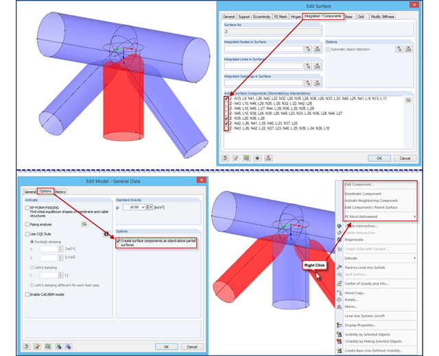
If intersections created in RFEM 4 are opened in an RFEM 5 file, the file management of intersections remains in the old format for compatibility reasons. Thus, the individual partial surfaces of the intersection can be activated or deactivated using only the "Integrated/Components" tab, all partial surfaces can only have the same thickness, and it is impossible to use the separate FE mesh refinement for the individual surface components.
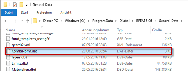
RFEM and RSTAB provide the option to create national annexes with user-defined partial safety factors and combination coefficients. They can also be transferred to other computers.

The following article describes the design of a single-span beam subjected to bending and compression, which is performed according to EN 1993‑1‑1 in the RF-/STEEL EC3 add-on module. Since the beam is modeled with a tapered cross-section and thus it is not a uniform structural component, the design must be performed either according to General Method in compliance with Sect. 6.3.4 of EN 1993‑1‑1, or according to the second-order analysis. Both options will be explained and compared, and for the calculation according to the second-order analysis, there is an additional design format using Partial Internal Forces Method (PIFM) available. Therefore, the design is divided into three steps: design according to Sect. 6.3.4 of EN 1993‑1‑1 (General Method), design according to the second‑order analysis, elastic (warping torsion analysis), design according to the second‑order analysis, plastic (warping torsion analysis and Partial Internal Forces Method).
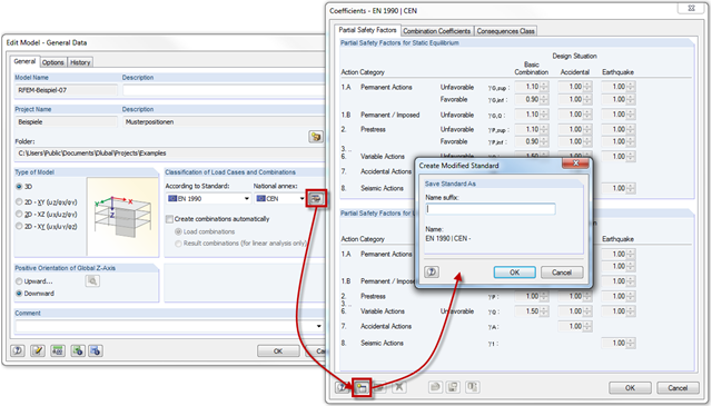
RFEM and RSTAB provide the option to create load and result combinations automatically according to the combination expressions defined in the standards. Partial safety factors and combination coefficients are specified in the standards or National Annexes. You can customize them as necessary and save them in a modified standard.
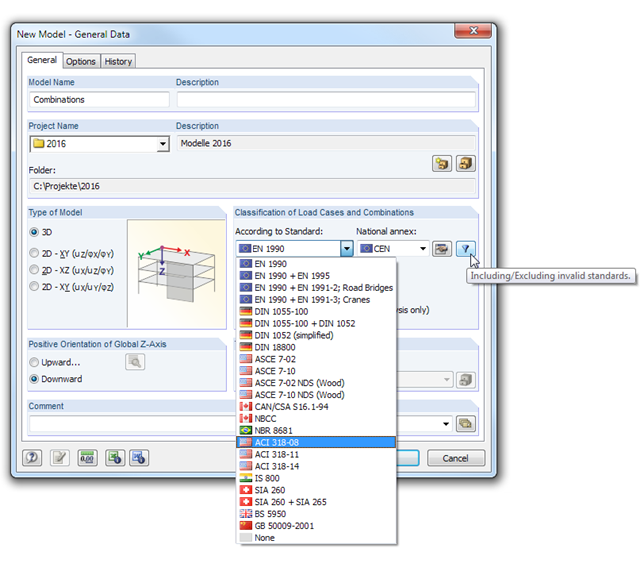
In RFEM and RSTAB, load cases can be combined automatically using combination coefficients (partial safety factors) in order to determine the required design situations.